ATX Power Supply Modification – Defeating Over-Current Shutdown
WARNING! – By attempting this modification you accept all risks, including, but not limited to, damage to the power supply. It should go without stating that this will void your warrantee.
Background
I am using an ATX power supply to drive a 12V car audio amplifier. At medium to high volumes, sudden changes in the music sound level would trip the over-current protection in the supply. The supply would then need to be unplugged for about a minute before it could be powered back on. Car amplifiers are designed to work from ~10.5V to ~14.5V, so a brief, small drop in voltage should not be an issue. The amplifier has its own fuse that will compensate for the removal of over-current within the supply.
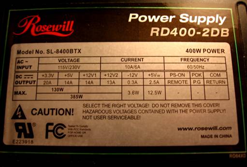
There are a range of ATX12V power supplies available, ranging in price from $15 to over $200. At ~ $35, the Rosewill supply would seem to be a mid-range power supply, but its features put it more on the low end. The RD400-2DB does not have true over-current protection; it only detects a momentary drop in voltage. Also, although the label implies there are two +12V rails, they are connected to the same +12V source inside the supply.
The modification is very simple for the Rosewill RD400-2DB power supply. This should work for any supply that uses the 2005ATX IC, but that hasn’t been tested. The procedure summary below will be enough for many people to modify their supply. The pictures below provide details on opening the case and lifting pin 5.
Procedure Summary
1. Connect PS_ON (usually green) to GROUND (black), power on the supply, and very briefly short the +12V wire to GROUND. The power supply should shut down, indicating that the over-current protection is working.
2. Open the case and lift pin 5 of the “2005AZ” PWM chip.
3. Repeat step one. This time the brief short should NOT shut down the supply.
Procedure Details
For reference, this picture shows the label for the Rosewill power supply.
Remove the four screws indicated by the red arrows. Note how the top cover slides into slots at the bottom of the sides. Carefully pry near the four corners to lift the top up. Be careful for the wires connecting the fan.
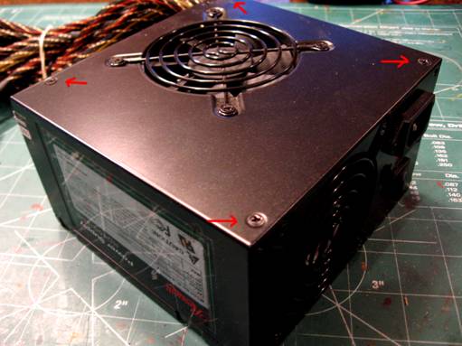
Rotate the cover up and off to the side. You may be able to unplug the fan, but the wires are long enough to move it out of the way. Cut the plastic wire tie that holds the bundle of power wires where they exit the case.
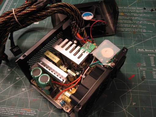
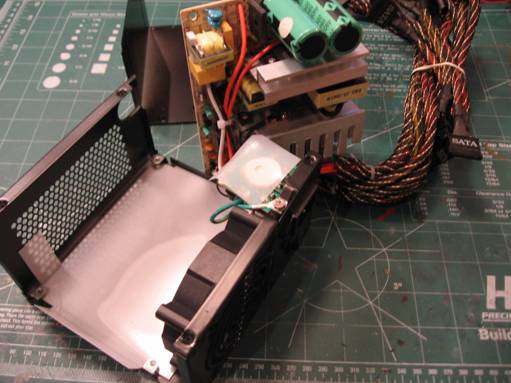
Remove the four screws that hold the PCB in place. Careful lift the PCB out and rotate it to the side.
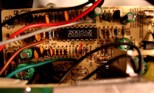
This picture shows the 2005AX PWM controller. Pin 1 is in the lower left of the IC. The red arrow points to pin 5.
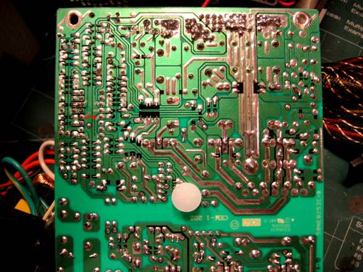
This is the back side of the PCB. Again, the red arrow points to pin 5. Desolder pin 5.
From the front side of the PCB, lift up pin 5.
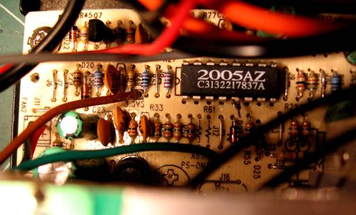
Here’s a picture of what the 2005AZ chip looks like after pin 5 has been lifted.
Reverse the above steps to reassemble the supply.
If desired, this process is reversible by simply reconnecting pin 5. Use a short jumper wire instead of trying to replace the pin into the PCB hole. There is less chance of damaging the IC this way.
EST7502B PWM IC
August 2012. Justin B. reported via e-mail that another chip used in ATX supplies is the EST7502B. He successfully powered an audio amp by grounding pins 3 & 4 of the IC.
The over-voltage and under-voltage detection in the EST7502B is much better than the ATX2005. EST7502B actually checks voltage ranges on each of the supplies individually. For the 12V supply, an external resistor divider should be on the board to drop the +12V supply down to ~ 3.5V. The under/over voltage protection checks for voltages in the range of 2.4V to 4.6V for the supply to be valid. +12V monitoring is via IC pin 3. Pin 3 can be left as-is.
IC pin 4 is a protection disable pin. Grounding pin 4 will disable the under-voltage protection on all voltage outputs. If pin 4 is connected on the board, you may need to lift/isolate the pin as shown above. Note that with under-voltage protection disabled, isolating and grounding pin 3 will also disable the over-voltage protection.
PS223 4-Channel Secondary Monitoring IC
April 2016. Nicolas Bouron reported via e-mail that, on a FSP250-60GEN power supply which uses the PS223 monitoring IC, disconnecting VS12A (pin 12) and VS12B (pin 8), defeated the over/under-voltage detection. A copy of the PS223 datasheet is available on the Silicon Touch Technology web site here:
http://www.siti.com.tw/product/spec/Power/SP-PS223-A.006.pdf or local copy here PS223.pdf.
Keywords:
ATX, ATX12V, over-current, protection, power supply modification
Reference:
Additional resources:
LAZAR's POWER ELECTRONICS GUIDE, http://www.smps.us/
If you have any comments or questions, feel free to contact me. I am especially interested in procedures that work for other brands of ATX supplies.
Kerry Imming – kcimming@pobox.com
Return to Kerry’s home page -> http://www.planetimming.com/
File: atx_mod.doc Last modified: April 3, 2016