Trace Repair on a Flex Cable DMD (Cherry)
- Use display diagnostics to display a pattern and find what
column(s) are not working. Count traces in flex cable to find the ones
that need to be repaired. Mark them with a Sharpie.
- You can try to press the flex cable back down with a popsicle stick. When I tried this I wound up with a few more non-working columns, but another person got the columns to work again.
- Very carefully cut out the flex cable for the broken column(s). I used an X-Acto knife. You must be careful not to break the neighboring traces. Scrape remaining adhesive from the glass contact with a toothpick.
- Reconnect the display to make sure that no additional columns have quit working. If they have, you’ll need to remove the flex cable for that one also and recheck.
- Find the resistor that drives one of the columns to be repaired and cut a length of 30 gauge wire long enough to connect the two. Strip 3/16” off one end and 1/8” off the other end.
- Melt a small blob of solder on the iron tip and heat the glass contact to tin it.
- Tin the 3/16” end of the wire. Lay it flat against the glass contact and heat to solder wire to glass contact.
- Wrap the wire to make contact to the printed circuit board pad and solder.
Below are pictures that show various steps in the process.
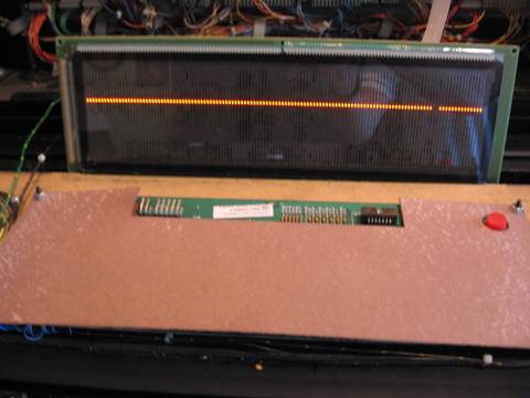
A digital picture taken during display diagnostics makes it easy to count the
columns to identify the bad ones.
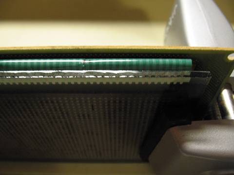
Count the traces in the flex cable to find the bad one(s). In this case it’s columns 117 & 118.
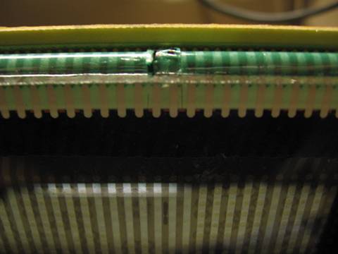
CAREFULLY cut between traces to separate the broken ones.
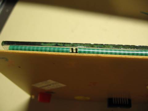
CAREFULLY remove the broken traces. Scrape the remaining adhesive off with a toothpick (not shown here).
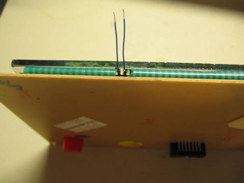
Melt a small blob of solder onto the iron tip and heat the contact pad on the DMD glass to tin it. Tin the end of a small piece of wire. Lay the wire on the pad and heat it to make a connection.
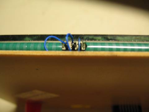
Wrap wire around and solder to printed circuit board. Note that I ended up replacing an additional column trace due to melting the edge with the soldering iron.
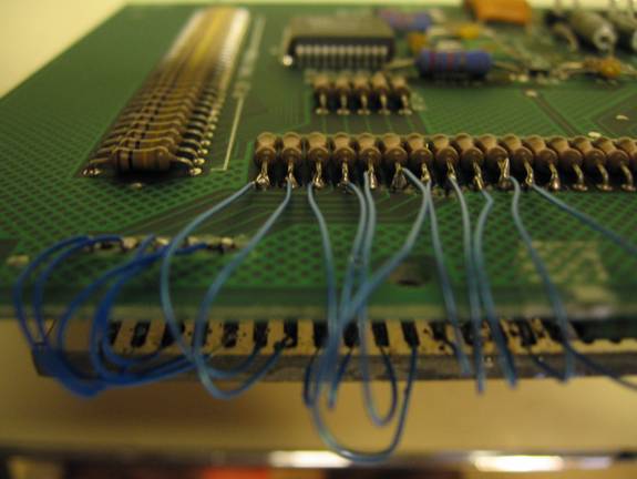
This picture shows a different DMD where I could wrap the rework wires around
the board and solder directly to the column series resistor. Add a filet of
solder to the resistor lead. Heat and insert the 1/8” end of wire to complete
the connection to the resistor lead.
Kerry Imming
File: DMD Repair.doc Last modified: October 15, 2009